Saturday, December 26, 2009

case study_ LUXEON Thermal Management Capabilities


LUXEON Thermal Management Capabilities


A key element in delivering quality high-power LEDs is managing the heat emitted from the LED chip. Advanced packaging technology provides LUXEON® power LEDs with unique thermal management capabilities. Using a thermal heatsink slug for the LED chip, heat is pulled away from the chip and can be transferred to a thermal management system. Because of the unique thermal design features and capabilities, LUXEON® LEDs can withstand the industry’s highest junction temperatures allowing for increased light output performance.


Case study_Lumen Maintenance

What is Lumen Maintenance?

Lumen maintenance simply compares the amount of light produced from a light source or from a luminaire when it is brand new to the amount of light output at a specific time in the future. For instance, if a luminaire produced 1000 lumens of light when it was brand new and now produces 700 lumens of light after 30,000 hours, then it would have lumen maintenance of 70% at 30,000 hours. Sometimes this is stated as lumen depreciation, which in our example would be 30% lumen depreciation from the original light output. Lumen maintenance is often specified as L50, L70, L80, or L90. In each case, L stands for lumen maintenance and the number is the percentage of light output remaining.
The appropriate lumen maintenance target is usually based on the application and the requirements set forth by customers. Since the human eye generally can’t detect a change in light output until there has been 30% depreciation, L70 is often established as the target for an application. With LUXEON LEDs, it generally takes tens of thousands of hours before the LUXEON LED will lose 30% of its initial light output.
Philips Lumileds technical advances in all areas have led to the industries longest lived, most reliable LEDs. LUXEON LEDs meet the LM-80 test criteria developed by the Illumination Engineering Society and the Department of Energy Solid State Lighting Standards Development group by a wide margin. Luminaire and lamp manufactures that use LUXEON LEDs can achieve Energy Star certification and ensure their products perform as promised.


What is Lumen Maintenance?

case study_Phillips


lilypad arduino


The LilyPad Arduino is a set of sewable electronic components that let you build your own soft, interactive fashion. To get started, snag a LilyPad deluxe kit, which has all of the available LilyPad sensor and actuator boards. Or, get only the pieces that you want, probably at least a LilyPad mainboard, FTDI board, power supply, and a spool of conductive thread. Work through the tutorials here to learn how to build all sorts of soft interactive stuff...perhaps fortune telling shirts, jackets that sing when you're squeezed or turn signal equipped cycling wear? Enjoy! Note: for a more general introduction to electronics, programming, and the regular (non-LilyPad) Arduino, see ladyada's excellent tutorials.

arduino mega


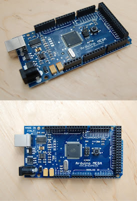
Arduino-Mega

Summary

Microcontroller ATmega1280 Operating Voltage 5V Input Voltage (recommended) 7-12V Input Voltage (limits) 6-20V Digital I/O Pins 54 (of which 14 provide PWM output) Analog Input Pins 16 DC Current per I/O Pin 40 mA DC Current for 3.3V Pin 50 mA Flash Memory 128 KB of which 4 KB used by bootloader SRAM 8 KB EEPROM 4 KB Clock Speed 16 MHz Power


The Arduino Mega can be powered via the USB connection or with an external power supply. The power source is selected automatically. External (non-USB) power can come either from an AC-to-DC adapter (wall-wart) or battery. The adapter can be connected by plugging a 2.1mm center-positive plug into the board's power jack. Leads from a battery can be inserted in the Gnd and Vin pin headers of the POWER connector. The board can operate on an external supply of 6 to 20 volts. If supplied with less than 7V, however, the 5V pin may supply less than five volts and the board may be unstable. If using more than 12V, the voltage regulator may overheat and damage the board. The recommended range is 7 to 12 volts.

The power pins are as follows: VIN. The input voltage to the Arduino board when it's using an external power source (as opposed to 5 volts from the USB connection or other regulated power source). You can supply voltage through this pin, or, if supplying voltage via the power jack, access it through this pin. 5V. The regulated power supply used to power the microcontroller and other components on the board. This can come either from VIN via an on-board regulator, or be supplied by USB or another regulated 5V supply. 3V3. A 3.3 volt supply generated by the on-board FTDI chip.

Maximum current draw is 50 mA. GND. Ground pins. Memory The ATmega1280 has 128 KB of flash memory for storing code (of which 4 KB is used for the bootloader), 8 KB of SRAM and 4 KB of EEPROM (which can be read and written with the EEPROM library). Input and Output Each of the 54 digital pins on the Mega can be used as an input or output, using pinMode(), digitalWrite(), and digitalRead() functions. They operate at 5 volts. Each pin can provide or receive a maximum of 40 mA and has an internal pull-up resistor (disconnected by default) of 20-50 kOhms. In addition, some pins have specialized functions: Serial: 0 (RX) and 1 (TX); Serial 1: 19 (RX) and 18 (TX); Serial 2: 17 (RX) and 16 (TX); Serial 3: 15 (RX) and 14 (TX). Used to receive (RX) and transmit (TX) TTL serial data. Pins 0 and 1 are also connected to the corresponding pins of the FTDI USB-to-TTL Serial chip. External Interrupts: 2 (interrupt 0), 3 (interrupt 1), 18 (interrupt 5), 19 (interrupt 4), 20 (interrupt 3), and 21 (interrupt 2).

These pins can be configured to trigger an interrupt on a low value, a rising or falling edge, or a change in value. See the attachInterrupt() function for details. PWM: 0 to 13. Provide 8-bit PWM output with the analogWrite() function. SPI: 50 (MISO), 51 (MOSI), 52 (SCK), 53 (SS). These pins support SPI communication, which, although provided by the underlying hardware, is not currently included in the Arduino language.

The SPI pins are also broken out on the ICSP header, which is physically compatible with the Duemilanove and Diecimila. LED: 13. There is a built-in LED connected to digital pin 13. When the pin is HIGH value, the LED is on, when the pin is LOW, it's off. I2C: 20 (SDA) and 21 (SCL). Support I2C (TWI) communication using the Wire library (documentation on the Wiring website). Note that these pins are not in the same location as the I2C pins on the Duemilanove or Diecimila. The Mega has 16 analog inputs, each of which provide 10 bits of resolution (i.e. 1024 different values). By default they measure from ground to 5 volts, though is it possible to change the upper end of their range using the AREF pin and analogReference() function.

There are a couple of other pins on the board: AREF. Reference voltage for the analog inputs. Used with analogReference(). Reset. Bring this line LOW to reset the microcontroller. Typically used to add a reset button to shields which block the one on the board. Communication The Arduino Mega has a number of facilities for communicating with a computer, another Arduino, or other microcontrollers. The ATmega1280 provides four hardware UARTs for TTL (5V) serial communication. An FTDI FT232RL on the board channels one of these over USB and the FTDI drivers (included with the Arduino software) provide a virtual com port to software on the computer.

The Arduino software includes a serial monitor which allows simple textual data to be sent to and from the Arduino board. The RX and TX LEDs on the board will flash when data is being transmitted via the FTDI chip and USB connection to the computer (but not for serial communication on pins 0 and 1). A SoftwareSerial library allows for serial communication on any of the Mega's digital pins. The ATmega1280 also supports I2C (TWI) and SPI communication. The Arduino software includes a Wire library to simplify use of the I2C bus; see the documentation on the Wiring website for details. To use the SPI communication, please see the ATmega1280 datasheet. Programming The Arduino Mega can be programmed with the Arduino software (download).

ArduinoBT


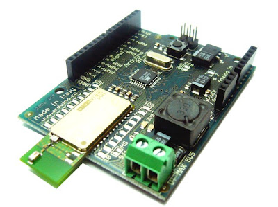
Arduino BT


The Arduino BT is an Arduino board with built-in bluetooth module, allowing for wireless communication.

In addition, it has some other differences from an Arduino NG:

The use of a DC-DC convertor, allowing the board to be powered with a minimum of 1.2 V, but with a maximum of 5.5 V. Higher voltages or reversed polarity in the power supply will kill the board.
A surface-mounted ATmega168 (as with the Arduino Mini). This doubles the amount of space available for your sketches and adds three more PWM pins and two more analog inputs.
Pin 7 is connected to the reset pin of the bluetooth module.

Only use serial communication at 115200 baud; this is the speed that the module has been configured to use.

The bluetooth module used is the Bluegiga WT11, iWrap version (details and datasheet [pdf]). The bluetooth module can be configured with commands set over the serial port from the ATmega168 (see the iWrap user's guide for details).

A program to set the name and pass code of the bluetooth module is run once on each Arduino BT. The name is set to ARDUINOBT and the pass code to 12345. For complete details, see the initializiation program's source code.

The ATmega168 comes preloaded with a bootloader that allows you to upload sketches to the board via bluetooth. The bootloader source code is available in the Arduino SVN repository.


plan2_development

12/17 (plan 2 development process)

To develop my idea (project), I've got to choose the most effective way; and among many

possible methods that I can use, I narrow down them to three: skype emoticon(open api)+

flash + arduino, .net program(microsoft) + arduino, java + arduino.

Also I am going to select one arduino board can efficiently works for my project.

- BT arduino ( bluetooth - for wireless)
- Lilly pad arduino ( for fabric)
- Mega arduino (controller)

-> or I can put bluetooth on lilypad arduino.

plan2

12/13 _ plan1 to 2

I decided to change MSN to Skype after checking their open API.
* They provides open space can share programs for free.
* Easy to set up new software(program) on skype
* The number of user and use(chat,phone)

plan1

Tuesday, December 15, 2009

Harry F. Harlow, Monkey Love Experiments


The famous experiments that psychologist Harry Harlow conducted in the 1950s on maternal deprivation in rhesus monkeys were landmarks not only in primatology, but in the evolving science of attachment and loss.

How did Harlow go about constructing his science of love? He separated infant monkeys from their mothers a few hours after birth, then arranged for the young animals to be “raised” by two kinds of surrogate monkey mother machines, both equipped to dispense milk.

One mother was made out of bare wire mesh. The other was a wire mother covered with soft terry cloth.

Harlow’s first observation was that monkeys who had a choice of mothers spent far more time clinging to the terry cloth surrogates, even when their physical nourishment came from bottles mounted on the bare wire mothers. This suggested that infant love was no simple response to the satisfaction of physiological needs. Attachment was not primarily about hunger or thirst.

Then Harlow modified his experiment and made a second important observation. When he separated the infants into two groups and gave them no choice between the two types of mothers, all the monkeys drank equal amounts and grew physically at the same rate. But the similarities ended there. Monkeys who had soft, tactile contact with their terry cloth mothers behaved quite differently than monkeys whose mothers were made out of cold, hard wire.

Harlow hypothesized that members of the first group benefitted from a psychological resource—emotional attachment—unavailable to members of the second. By providing reassurance and security to infants, cuddling kept normal development on track.

What exactly did Harlow see that convinced him emotional attachment made a decisive developmental difference? When the experimental subjects were frightened by strange, loud objects, such as teddy bears beating drums, monkeys raised by terry cloth surrogates made bodily contact with their mothers, rubbed against them, and eventually calmed down. Harlow theorized that they used their mothers as a “psychological base of operations,” allowing them to remain playful and inquisitive after the initial fright had subsided. In contrast, monkeys raised by wire mesh surrogates did not retreat to their mothers when scared. Instead, they threw themselves on the floor, clutched themselves, rocked back and forth, and screamed in terror.


Harry.F.Harlow's experiment can be applied to my project as a theoritical base.

- How to solve the emotional isolation in virtual space.
- Why do I need physical effects to solve the lack of communication in aspects of interaction.